BowFlex BXT8J Treadmill Assembly Video

Video Transcript:

BowFlex. Introducing the BowFlex, BXT8J, Assembly Video.

Before you begin the assembly, please make sure you read the assembly manual thoroughly, as it contains important safety warnings, and assembly tips.

See the assembly manual for a complete parts list.

Begin by selecting an area where you are going to set up, and operate your machine.

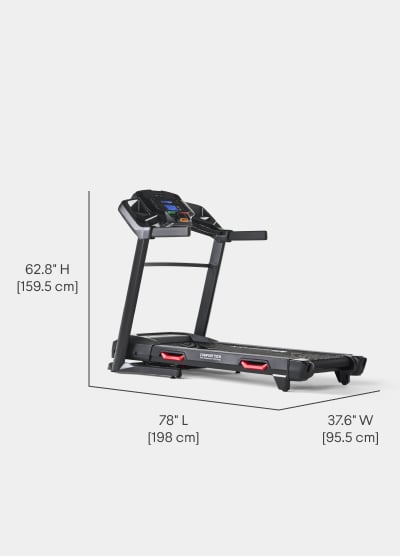
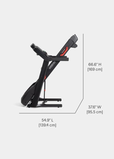
For safe operation, the location must be on a hard, level surface. Allow a minimum workout area of 77 inches, by 157 inches.

Be sure that the workout space you are utilizing has adequate height clearance, taking into consideration the height of the user and the maximum incline of the machine.

The following tools are recommended for this assembly. Tools Included: number two, Phillips screwdriver / 6mm Allen Wrench

(Tools Not Included: Box cutter and scissors.)

Please Note: Select pieces of Hardware have been provided as spares on the Hardware Card. Be aware that there may be remaining Hardware after the proper assembly of your machine.

Step 1

DO NOT CUT the Shipping Strap on the Base Assembly until it has been placed face up, as shown in the appropriate work space.

Begin by moving the machine to your final location, and cutting the Shipping Strap on the Base Assembly.

Make sure that there is safe clearance around, on and above your treadmill, and that there is adequate height clearance for the raised deck.

Using the support bar found below the rear of the walking belt, lift the walking deck fully upward, and engage the hydraulic lift. Be sure that the hydraulic lift is correctly locked in place. Use proper safety precautions, and lifting techniques. Use a second person if necessary.

Do not use the walking belt or rear roller to lift the treadmill. These parts do not lock in place, and can abruptly move.

Make sure that the locking mechanism is engaged.

Carefully pull back on the Walking Deck and make sure that it does not move. When you do this, keep clear of movement path in case the treadmill lock is not engaged.

Do not lean against the treadmill when it is folded.

Step 1 is now complete.

Step 2

Begin step two by locating the Left, and Right Uprights. Connect the Cables from the Right Upright, and Attach the Uprights to the Frame. Make sure not to pinch, or cut the cables. Please note, the Hardware is pre-installed, and not supplied in the Hardware Bag.

Remove the Hardware from the uprights, and with some assistance, set them on the frame one at a time. Once in place, insert the side, and top Hardware.

Hand tighten the Hardware for now. Do not fully tighten the Hardware until instructed at a later step. Secure both the right, and left uprights.

Step two is now complete.

Step 3

Slightly push the walking deck forward toward the front of the machine.

With your left foot, lightly push the top part of the hydraulic lift forward until the locking tube releases, and you can pull the walking deck slightly toward the rear of the machine.

Hold up the rear of the walking deck, and move to the side of the machine. Please note, keep clear of the movement path of the walking deck.

The hydraulic lift is set up to drop lightly. Hold onto the walking deck until approximately 2/3 of the movement down. Make sure that you use proper lifting technique; the walking deck can possibly drop quickly in the last part of the movement.

Step 3 is now complete.

Step 4

Start by locating the Console Assembly, and flipping it over. Next, Remove the Console Backing from the Console Assembly.

Start by Removing the Hardware using the provided number two, Phillips screwdriver. Dispose of the pre-installed Hardware. Remove the Console Backing, and place it aside for now.

Step 4 is now complete.

Step 5

Begin by attaching the Console Assembly to the Left, and Right Uprights. Take care not to pinch or cut the cables.

NOTICE: Be sure that the hooks on each side of the Console are seated in the notches on the Uprights.

The Hardware is pre-installed, and not supplied in the Hardware Bag.

Insert the Hardware as shown, and hand tighten the Hardware for now. Do not fully tighten the Hardware until instructed at a later step. Secure the Hardware on both sides.

With the Console Assembly Attached, Connect the Right Console-Assembly Cables to the Right Upright. Remove the zip tie and rubber bands, that attach the Cables. Attach the Cables, and take care not to pinch or cut the cables.

Step 5 is now complete.

Step 6

Begin step 6 by attaching the Crossbar to the Uprights. If necessary, loosen the screws from Step 5 to make installation of the Crossbar easier.

Place the Crossbar in between both Uprights. The Hardware is pre-installed, and not supplied in the Hardware Bag.

Insert the Hardware as shown, and hand tighten the Hardware for now. Do not fully tighten Hardware until instructed at a later step. Secure the Hardware on both sides.

Step 6 is now complete.

Step 7

Begin step 7 by attaching the Cupholders to the Console. Slowly lower, and set the Cupholders in place. The Cupholder edges should be flush with the face of the Console.

Locate the Provided Part A, Self-Tapping Screws, and insert them through the bottom of the Console Assembly.

Fully tighten the Screws using the provided number two, Phillips screwdriver. Tighten All Six Screws.

Step 7 is now complete.

Step 8

Fold the Walking Deck as shown on step 1, and tighten ALL Hardware from previous steps. Fully tighten the Hardware from ALL previous steps, using the provided Allen Wrench.

After all Hardware is secured, step 8 is now complete.

Step 9

Begin step 9 by attaching both the Left, and Right Base Shrouds to the Frame Assembly. The Hardware is pre-installed, and not supplied in the Hardware Bag.

Insert the Hardware as shown, and fully tighten Hardware using the provided number two, Phillips Screwdriver. Secure the Hardware on both sides, and on both ends of the Shrouds.

After the Hardware is secured, unfold the Walking Deck. Unfold the Walking Deck, only after the Base Shrouds have been attached to the Frame Assembly.

Step 9 is now complete.

Step 10

Begin step 10 by attaching the Console Backing to the bottom of the Console Assembly. Slowly set it in place. Secure the Console Backing using the provided Part B, Self-Tapping Screws.

Attach the Hardware marked with the number 1 first, then the Hardware with the number 2, followed by the remaining Hardware.

Fully tighten the Screws using the provided number two, Phillips screwdriver.

Step 10 is now complete.

Step 11

Begin step 11 by attaching the Handlebar Shrouds to the Frame Assembly. Slide the Handlebar Shrouds onto the handlebars.

Be sure the tabs on the shrouds snap onto the Console.

Step 11 is now complete.

Step 12

Start by Connecting the Safety Key to the Bottom, front-center of the Console Assembly. Slowly insert the Key into place.

Next, Connect the Power Cord to the Frame Assembly. Connect this machine to a properly grounded outlet only. See Grounding Instructions for more information.

Congratulations! Assembly of the BowFlex, BXT8J is now complete!

Make a final inspection. Inspect your machine to ensure that all Hardware is tight, and components are properly assembled.

Do not use until the machine has been fully assembled and inspected for correct performance in accordance with the Assembly Manual.

Brought to you by BowFlex.