Getting Started: The Treadmill 10

-
Shipping Details
See Shipping Information Check Order StatusExpected Delivery Items
# of Packages: Package Size & Weight 1 89.1" L x 35" W x 18.7" H
(226.3 x 88.9 x 47.5 cm) 350.9 lbs
(159.2 kg) -
Preparing Your Space
Preparing Your Space
Select the area where you are going to set up and operate your machine. For safe operation, the location must be on a hard, level surface. Allow a minimum workout area of 79" x 164" (200.5 x 416 cm). Be sure that the workout space you are utilizing has adequate height clearance, taking into consideration the height of the user and the maximum incline of the machine.
Enhancing Your Experience
The BowFlex Dual Mat is an optional accessory that helps keep your workout area clear and adds a layer of protection to your floor. The rubber machine mat provides a non-slip, rubber surface which limits static discharge and reduces the possibility of display errors. If possible, put your Dual Mat in your selected workout area before you begin assembly.
Specs
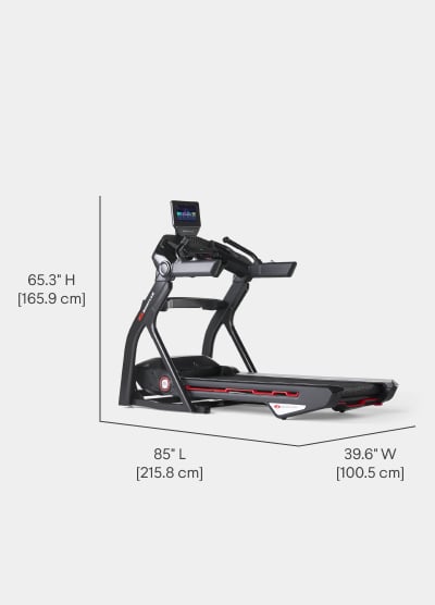
Dimensions
85" L x 39.6" W x 65.3" H
(215.8 x 100.5 x 165.9 cm)
Console w/ HD Touchscreen
10"
(25.4 cm)
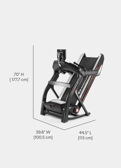
Stowed Dimensions
44.5" L x 39.6" W x 70" H
(113 x 100.5 x 177.7 cm)
Product Weight
323 lbs
(146.5 kg)
Minimum Ceiling Height
User Height + 12.4"
(User Height + 31.5 cm)
Maximum User Weight
400 lbs
(181.4 kg)
-
Assembly & Manuals
-
Warranty & Registration
Warranty
Frame
15 Years
Mechanical Parts
5 Years
Electronics & HD Touchscreen
1 Year
Labor
2 Years
Purchasing a Bowflex Treadmill 10? Check out the Bowflex Protection Plan to upgrade your standard warranty.
Upgrade Your WarrantyYou can also Register your product here if purchased through one of our retail partners. If you purchased directly through bowflex.ca, your product is already registered.
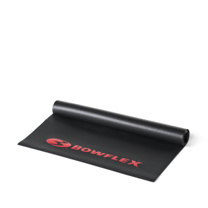 BowFlex Dual Mat

